Variable Power Supply


Variable Power Supply
Ready Project work Like
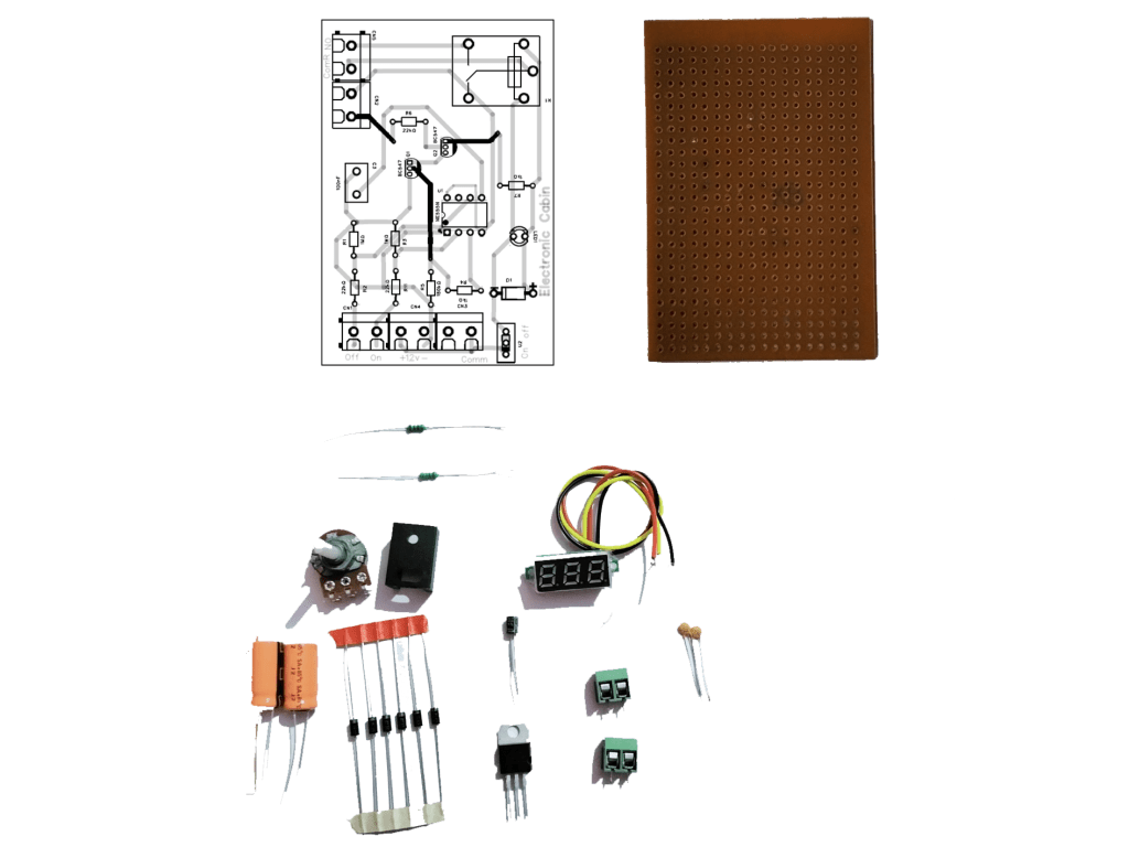
Required Components
1. Zero PCB
2. Circuit Lyout
3. PBT 2, 2 nos Connecter
4. 1000uf, 25volt Capacitor
5. 10uF, 25 Volt Cpacitor
6. 230v to 12v transformer
7. 1N4007 Diod 5 Nos
8. 5k Ohms Potentio Meter
9. Led Bulb
19. LM317 Voltage Regulater
11. 1k Ohms resistor
12. 220 Ohms Resistor
13. seven Segment Voltme
14. 104 Pf
Working of components
1. Zero PCB
“Zero PCB” is a term that is used to refer to a printed circuit board (PCB) with no components soldered onto it. It is essentially a bare PCB that has been manufactured with the necessary conductive tracks, pads, and vias for mounting components. Zero PCBs are often used as a starting point for building custom electronic devices, such as a custom-designed microcontroller board, or for testing and debugging purposes.
A zero PCB can be populated with components by soldering the components onto the pads, connecting the components together with wire, and adding any necessary power connections. Once the components are installed, the zero PCB can be used as a custom-designed circuit board for a wide range of applications, including control systems, data acquisition systems, and communication systems, among others.
Zero PCBs can be manufactured using a variety of techniques, including etching, plating, drilling, and photo-plotting, and can be made from a variety of materials, including fiberglass, aluminum, and flexible substrates. The choice of technique and material will depend on the specific requirements of the application and the desired characteristics of the final circuit board, such as its size, thickness, and durability.
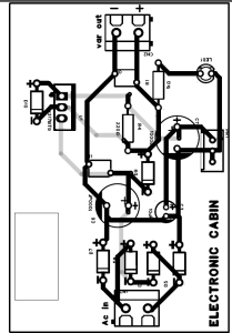
2. Circuit Lyout
Circuit layout is an essential step in the process of making a printed circuit board (PCB). It involves the placement of components and the routing of interconnections on the PCB. Here is a basic outline of the steps involved in creating a circuit layout for a PCB:
Schematic Design: Start with a schematic diagram that defines the electrical connections between components. This is a high-level view of the circuit and provides the basis for the circuit layout.
Component Placement: Place the components on the PCB in a manner that minimizes the length of interconnections, reduces the potential for interference, and provides adequate clearance for cooling. Consider factors such as component size, electrical requirements, and manufacturing constraints.
Interconnection Routing: Route the interconnections between components on the PCB. This includes the routing of power and ground lines, signal lines, and other connections. Consider factors such as electrical performance, interference, and manufacturing constraints.
Design Rule Check (DRC): Perform a design rule check (DRC) to ensure that the circuit layout complies with manufacturing requirements and guidelines. The DRC checks for issues such as minimum trace width, minimum spacing between traces, and minimum clearance between components.
Design for Manufacturability (DFM): Optimize the circuit layout for manufacturability by considering factors such as panelization, routing direction, and trace thickness. This step can help to reduce the cost of manufacturing and improve the yield of the final product.
Final Review: Review the circuit layout for accuracy, compliance with requirements, and overall quality. Consider factors such as electrical performance, manufacturability, and regulatory compliance.
Output Files: Generate the final output files that are used to fabricate the PCB. This includes Gerber files, drill files, and other required outputs.
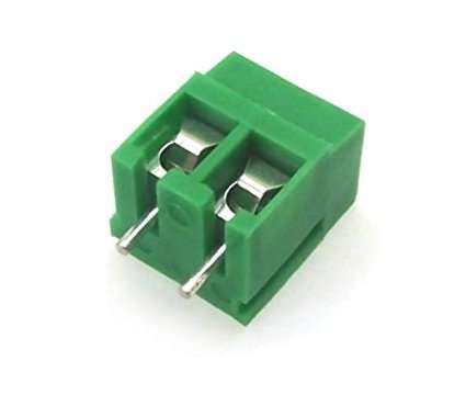
3. PBT 2 Connector
“PBT 2 connectors” likely refers to connectors made from Polybutylene Terephthalate (PBT) material that have two pins or contacts.
PBT is a thermoplastic polymer commonly used in the manufacture of electrical and electronic components due to its high temperature resistance, dimensional stability, and chemical resistance. Connectors made from PBT can be used in a wide range of applications, including data communication, power distribution, and signal transmission.
A PBT 2 connector typically consists of two pins or contacts that are inserted into mating connectors to establish an electrical connection. The number of pins or contacts can vary, depending on the specific requirements of the application, and the connectors may be designed for use with a specific type of cable or interface.
PBT 2 connectors are used in a variety of electronic devices and systems, including computers, consumer electronics, and telecommunications equipment. They are designed to provide a reliable and durable connection between components, and can be customized to meet the specific requirements of the application, such as size, shape, and electrical specifications.
The use of PBT 2 connectors can provide several benefits, including improved reliability and performance, reduced assembly time, and reduced production costs. However, it is important to carefully consider the specific requirements of the application when selecting a PBT 2 connector, as different types of connectors may be better suited for different applications.
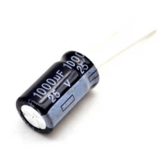
4. 1000uF, 25 volt Capacitor
A 1000uF, 25V capacitor connected to a rectifier circuit can be used for several purposes, including:
Filtering: The capacitor can be used to filter out the pulsating DC output from the rectifier, resulting in a smoother and more stable DC voltage.
Energy Storage: The capacitor can store energy from the rectifier and provide it to the load during periods when the rectifier output voltage is low.
Voltage Regulation: The capacitor can be used to regulate the DC voltage output from the rectifier, providing a stable voltage source to the load.
In a typical application, the positive lead of the capacitor is connected to the positive output of the rectifier, and the negative lead of the capacitor is connected to the negative output of the rectifier. The size of the capacitor and the operating voltage of the rectifier will determine the capacitance and voltage ratings of the capacitor.
It is important to observe the voltage rating of the capacitor and not exceed it, as it can result in damage to the capacitor and potentially the circuit. Additionally, it is important to properly size the capacitor to meet the requirements of the load and the rectifier circuit to ensure stable operation.
5. 10uf, 25 volt Capacitor
A 10uF, 25V capacitor is an electrolytic capacitor commonly used in electronics for several purposes, including:
Filtering: Capacitors can be used to filter out high-frequency noise in electronic circuits.
Energy Storage: Capacitors can store electrical energy and release it when needed to supply a load.
Coupling: Capacitors can be used to couple signals between stages of an electronic circuit.
Decoupling: Capacitors can be used to suppress high-frequency noise in power supply lines.
Bypassing: Capacitors can be used to bypass low-frequency noise in power supply lines.
The value of the capacitance and the voltage rating of the capacitor will determine its application in a given circuit. It is important to observe the voltage rating of the capacitor and not exceed it, as it can result in damage to the capacitor and potentially the circuit. Additionally, it is important to properly size the capacitor to meet the requirements of the load and the circuit to ensure stable operation.
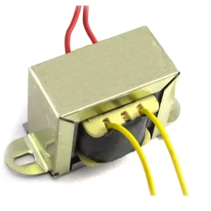
6. 230v to 12v Transformer
A 230V to 12V transformer is an electrical device that converts high voltage, low current AC power from the main electrical supply (230V) to low voltage, high current AC power (12V). It is commonly used to power low voltage electrical devices such as lights, motors, and other devices that require a lower voltage than the main supply.
The transformer consists of a magnetic core around which two or more coils of wire are wound. The primary coil is connected to the input voltage, and the secondary coil is connected to the load. When AC voltage is applied to the primary coil, it generates a magnetic field that induces a voltage in the secondary coil. The voltage in the secondary coil is proportional to the turns ratio of the two coils.
It is important to select the correct transformer for the intended application based on the power requirements of the load, the frequency of the input voltage, and the voltage regulation requirements of the circuit. Overloading the transformer or using a transformer that is not properly rated for the load can result in damage to the transformer, the load, or both.
7. 1N4007 Diod
The 1N4007 diode is a general-purpose, rectifying diode commonly used in electronic circuits. It is rated for a maximum reverse voltage of 1000V and a maximum forward current of 1A.
The main function of the diode is to allow current to flow in only one direction (forward direction), while blocking the flow of current in the opposite direction (reverse direction). This makes it ideal for use in applications such as rectifying AC to DC, voltage protection, and voltage clamping.
In addition to its rectifying properties, the 1N4007 diode has a relatively fast recovery time and low forward voltage drop, making it suitable for high frequency applications.
When selecting a diode for a particular application, it is important to consider factors such as the voltage and current ratings, recovery time, and voltage drop to ensure that the diode meets the requirements of the circuit and will perform as expected.

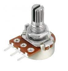
8. 5k Ohms Potentiometer
A 5k ohm potentiometer is an adjustable resistor used to control the flow of electrical current in a circuit. Potentiometers are commonly used as volume controls, position sensors, and as adjustable voltage dividers.
The resistance of a potentiometer is controlled by a sliding contact, known as the wiper, that moves along a resistive track. The wiper can be connected to either the two end terminals of the resistive track, forming a voltage divider, or to a single terminal and a ground, forming a rheostat.
In a 5k ohm potentiometer, the total resistance of the resistive track is 5 kilo-ohms. The resistance between the wiper and one end terminal is proportional to the position of the wiper along the track. By adjusting the position of the wiper, the resistance in the circuit can be changed, which affects the voltage drop across the resistive track and therefore the current flowing through the circuit.
When selecting a potentiometer, it is important to consider the total resistance, the power rating, the resolution (i.e., how fine the adjustment can be made), and the type of adjustment mechanism (e.g., rotary or linear). Additionally, it is important to make sure the potentiometer is compatible with the circuit and will perform as expected in the intended application.
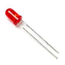
9. LEDs
An LED (Light Emitting Diode) is a type of semiconductor device that emits light when an electric current passes through it. LEDs are widely used in a variety of applications, including display panels, automotive lighting, traffic signals, lighting fixtures, and consumer electronics.
LEDs are highly efficient and long-lasting compared to traditional light sources, and they can be produced in a range of sizes, shapes, and colors. LEDs are often used in lighting applications because they are energy-efficient, have a long lifespan, and produce very little heat.
LEDs operate by passing a current through a semiconductor material, which excites electrons and causes them to emit light. The color of the light depends on the composition of the semiconductor material and the energy of the electrons.
LEDs are connected in series or parallel circuits and are driven by a constant current or constant voltage source. It is important to choose an appropriate power supply for the LEDs and to properly match the voltage and current requirements of the LEDs to the power supply.
LEDs are highly reliable and durable and can be used in a wide range of environmental conditions. However, it is important to follow manufacturer specifications and safety guidelines when using LEDs to ensure proper operation and prevent damage to the devices.
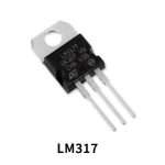
10. LM317 voltage regulator
The LM317 has a wide input voltage range, from 3V to 40V, and can provide a regulated output voltage between 1.25V and 37V. The output voltage can be easily set using two external resistors, and the LM317 also has a built-in thermal overload protection and short-circuit protection to ensure safe operation.
11. 1k ohms Resistor
A 1k Ohm resistor is a passive electronic component that resists the flow of electrical current with a resistance value of 1,000 Ohms. It is commonly used in various electronic circuits to limit the flow of current, divide voltage, or provide over-current protection.
1k Ohm resistors are widely available and come in various physical sizes and package types, including through-hole and surface-mount packages. They can also be used in both high and low-power applications, and their compact size makes them ideal for use in compact circuit designs.
When selecting a 1k Ohm resistor, it is important to consider the maximum power rating, tolerance, and temperature coefficient of the resistor, as well as the operating temperature range and ambient conditions of the circuit. These specifications will determine the suitability of the resistor for a specific application.
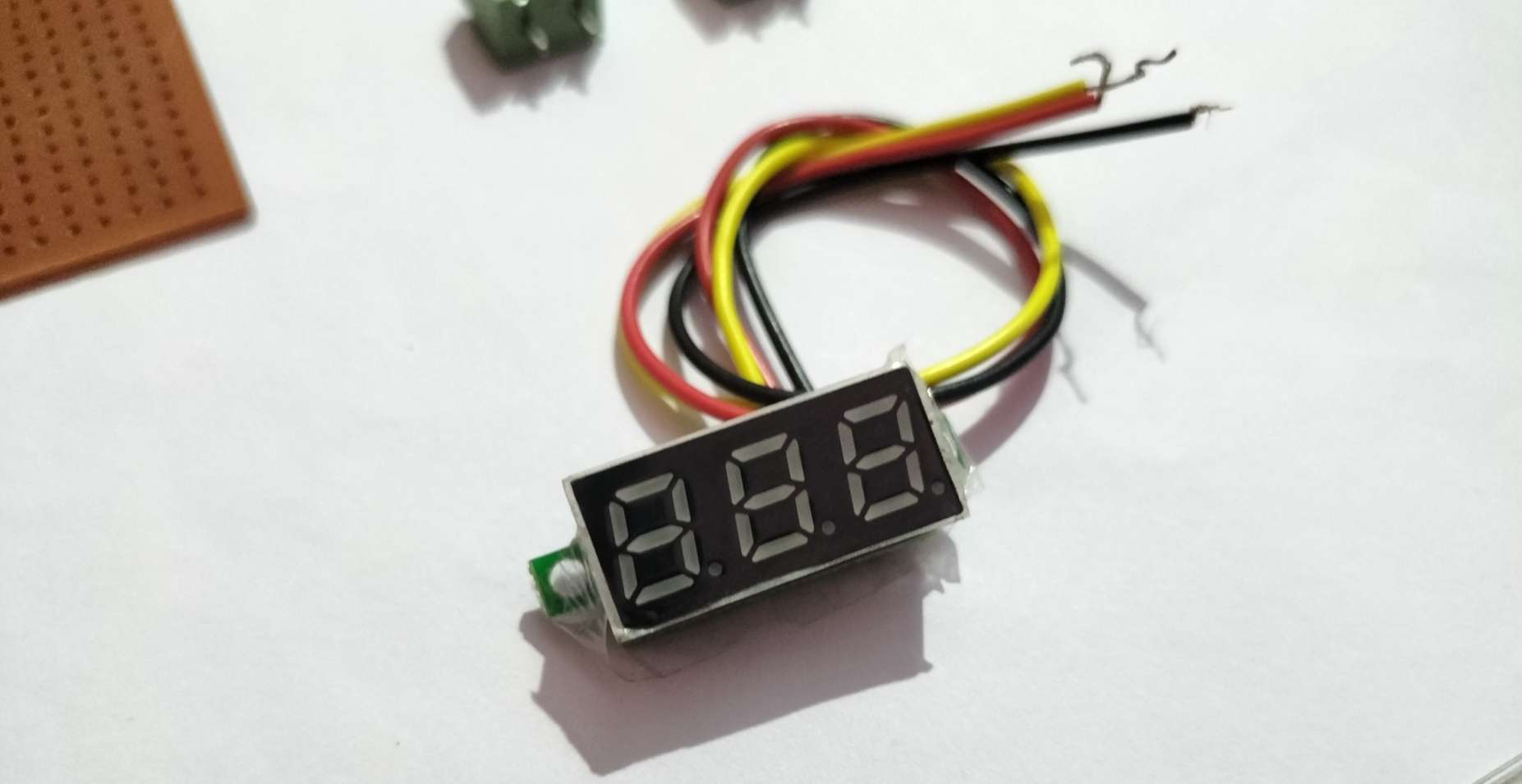
12. Seven Segment Voltmeter
A small seven segment voltmeter is a type of digital voltmeter that uses seven segments to display the voltage measurement. It provides a compact and simple solution for measuring voltage levels in various applications. The segments can be either light emitting diodes (LEDs) or liquid crystal displays (LCDs). They are usually powered by a DC voltage source and display the measurement in a numerical format.
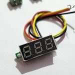
How to Connect Volt Meter
Red wire: Connect it to the positive voltage supply.
Black wire: Connect it to ground or negative voltage.
Yellow wire: Connect it to the voltage source that you want to measure.
It’s important to refer to the datasheet or manual of the voltmeter for specific instructions and diagrams, as the wiring configuration may vary depending on the voltmeter’s design.
Note: Always make sure to connect the wires according to the correct polarity, as connecting them in reverse can damage the voltmeter and/or other components in the circuit.