
Basic Program Of ESP32
NODMCU EPS32 basic Programing
This is basic program of ESP32, in this circuit we are using relay module wich you can connect any load Ac or dc and load capasicty is upon relay.there are four relays we are using and four push buttons which will oprate our four relays. so lets start
Required Components
- ESP 32
- 4 LEDs or Other Load
- 4 Push Buttons
- 4 Relay Modules
- Power Supply
Datail of Components
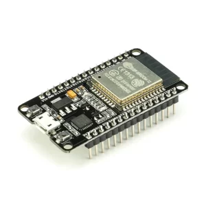
1. NodeMcu ESP32
ESP32 is a series of low-cost, low-power system on a chip microcontrollers with integrated Wi-Fi and dual-mode Bluetooth. NODMCU is a firmware that runs on the ESP32, providing an environment for programming and control.
PinOut
ESP32 pinout includes various pins for power supply, GPIOs, ADC, UART, SPI, I2C, etc. Here is a list of the most commonly used ESP32 pins:
- Power Pins: 3V3, GND, EN
- GPIO Pins: 0 to 39
- ADC Pins: A0 to A9
- UART Pins: TX0, RX0, RTS0, CTS0
- SPI Pins: MISO, MOSI, SCK, CS
- I2C Pins: SDA, SCL
It is important to note that not all the ESP32 boards have the same pinout and you should refer to the specific board documentation for the exact pin configuration.
2. LEd
LED stands for Light Emitting Diode, a type of semiconductor that produces light when a current passes through it. LEDs are used in many applications, including lighting, displays, signals, and indicators. They are known for their energy efficiency, long lifespan, and versatility.
3. Push Button
A mini push button is a compact version of a standard push button, designed for applications where space is limited. Mini push buttons are commonly used in small electronic devices, such as mobile phones, handheld gaming devices, and portable music players. They often have a smaller button size, lower profile, and require less activation force than larger push buttons. Some mini push buttons also have additional features, such as illuminated buttons or touch-sensitive activation.
4. Relay module
A relay is an electrically operated switch that allows a low-power circuit to control a high-power circuit. It works by using an electromagnet to move a switch that then opens or closes a circuit.
A relay module is an electronic device that contains one or more relays, along with the necessary control circuitry. The purpose of a relay module is to provide a convenient and compact way to interface relays with a microcontroller or other control system. A relay module typically has a set of input pins for controlling the relay(s), and a set of output pins for connecting the controlled devices. Some relay modules also include additional features, such as LED indicators, protection circuitry, or optocouplers, to enhance their functionality and reliability. Relay modules are widely used in various projects and applications, such as controlling motors, lights, and other electrical devices, and for interfacing with sensors and other digital signals.
5. Power Supply
The ESP32 microcontroller module is designed to operate at a voltage level of 3.3V. Using a voltage higher than 3.3V may damage the device. The voltage regulator on the ESP32 board is typically used to regulate an input voltage in the range of 4V to 20V down to the required 3.3V operating voltage.
While the voltage regulator may be capable of handling input voltages up to 20V, it is important to consult the datasheet for the specific ESP32 module for the recommended input voltage range and any other specific requirements for the voltage drop across the power supply. Additionally, some ESP32 modules may have protection circuits or other components that are designed to limit the voltage and current applied to the device, so it is important to ensure that the power supply meets the specified requirements to ensure safe and reliable operation.
Connections
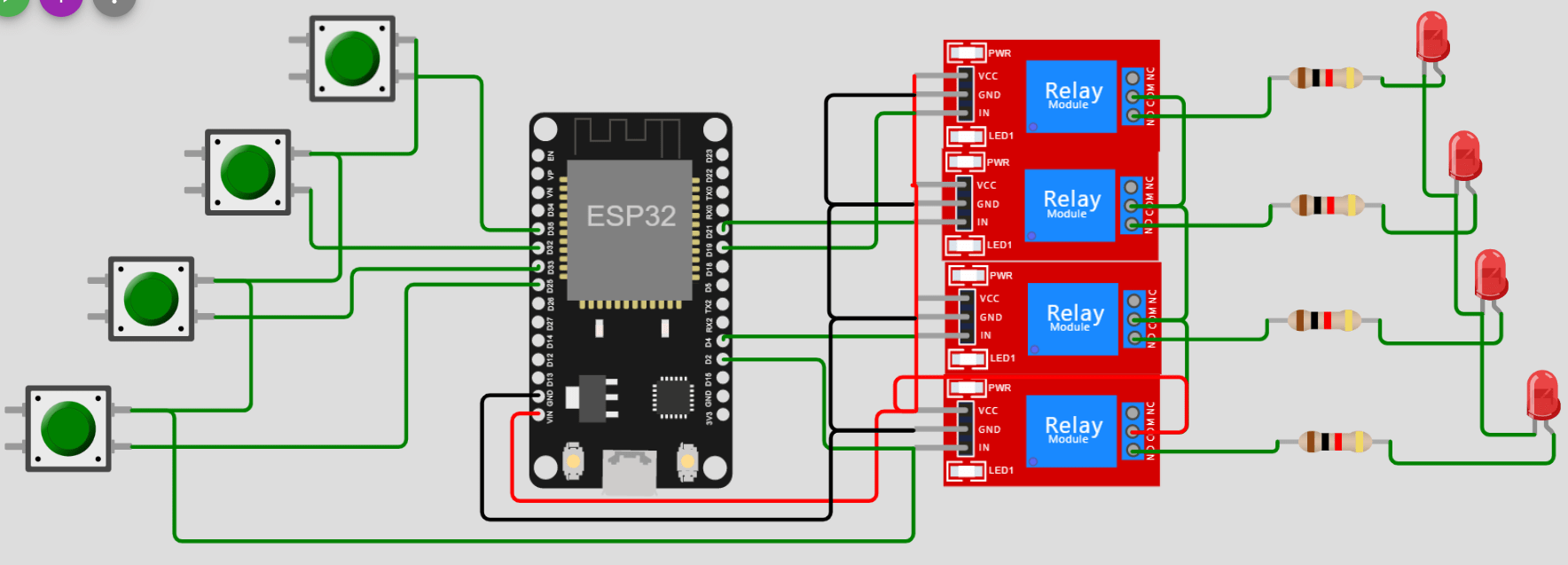
The connection of 4 relays to an ESP32 microcontroller will typically involve the following steps:
Supply power to the ESP32 and the relays: Connect the positive terminal of the power supply to the VCC of the ESP32 and the positive terminal of the relay module. Connect the negative terminal of the power supply to the GND of the ESP32 and the negative terminal of the relay module.
Connect the relay control signals to the ESP32: The relay control signals are typically connected to the GPIO pins of the ESP32. The specific GPIO pins to be used will depend on the relay module and the specific requirements of the application.
Connect the relay coil pins to the power supply: The coil pins of the relays are typically connected to the positive terminal of the power supply, so that the ESP32 can turn on and off the relays by controlling the GPIO pins.
Connect the relay contact pins to the load: The contact pins of the relays are typically connected to the load that needs to be controlled by the ESP32, such as an LED, a motor, or a solenoid.
It is important to consult the datasheet for the specific ESP32 module and the relay module for the recommended operating conditions, pin configurations, and other specific requirements. Additionally, it is important to ensure that the power supply, relay module, and ESP32 are all connected correctly and that the voltage levels and current requirements are met to ensure safe and reliable operation.
1. ESP32 Pin no. D2, D4, D19, D21 are OutPut Pins, Connect relay control signals in to those pins four pins four relays.
2. pin no. D25, D33, D32, D35 are all input pins we can connect it to push buttons and give input 3 volt to other side of the pushbuttons
3. now give input positive supply to the relay comm terminal, and NO of the relay connect to the resistor through led, now connect negative supply to the led negativ
Time to code (my favorite part )
Copy the code and paste to IDE
					int ButtonState = 0 ;
void setup(){
//Button Pins
  pinMode(25, INPUT);
  pinMode(33, INPUT);
  pinMode(32, INPUT);
  pinMode(35, INPUT);
  //Relay Pins
  pinMode(2, OUTPUT);
  pinMode(4, OUTPUT);
  pinMode(19, OUTPUT);
  pinMode(21, OUTPUT);
}
void loop(){
  ButtonState= digitalRead(25);
  if(ButtonState==HIGH){
    digitalWrite(2,HIGH);
  }else{
    digitalWrite(2,LOW);
  }
  ButtonState = digitalRead(33);
  if(ButtonState==HIGH){
    digitalWrite(4,HIGH);
  }else{
    digitalWrite(4,LOW);
  }
  ButtonState=digitalRead(32);
  if(ButtonState==HIGH){
    digitalWrite(21,HIGH);
  }else{
    digitalWrite(21,LOW);
  }
  ButtonState=digitalRead(35);
  if(ButtonState==HIGH){
    digitalWrite(19,HIGH);
  }else{
    digitalWrite(19,LOW);  }

}